En arrêtant de fumer, il est courant d’avoir des envies de grignotage. Vos envies de sucre augmentent pour compenser le manque. Ce qui n’est pas sans conséquence pour la santé, et même pour la ligne. Il existe quelques petites astuces pour pallier ce nouveau besoin et...
Le site des ex-fumeurs et fiers de l’être !


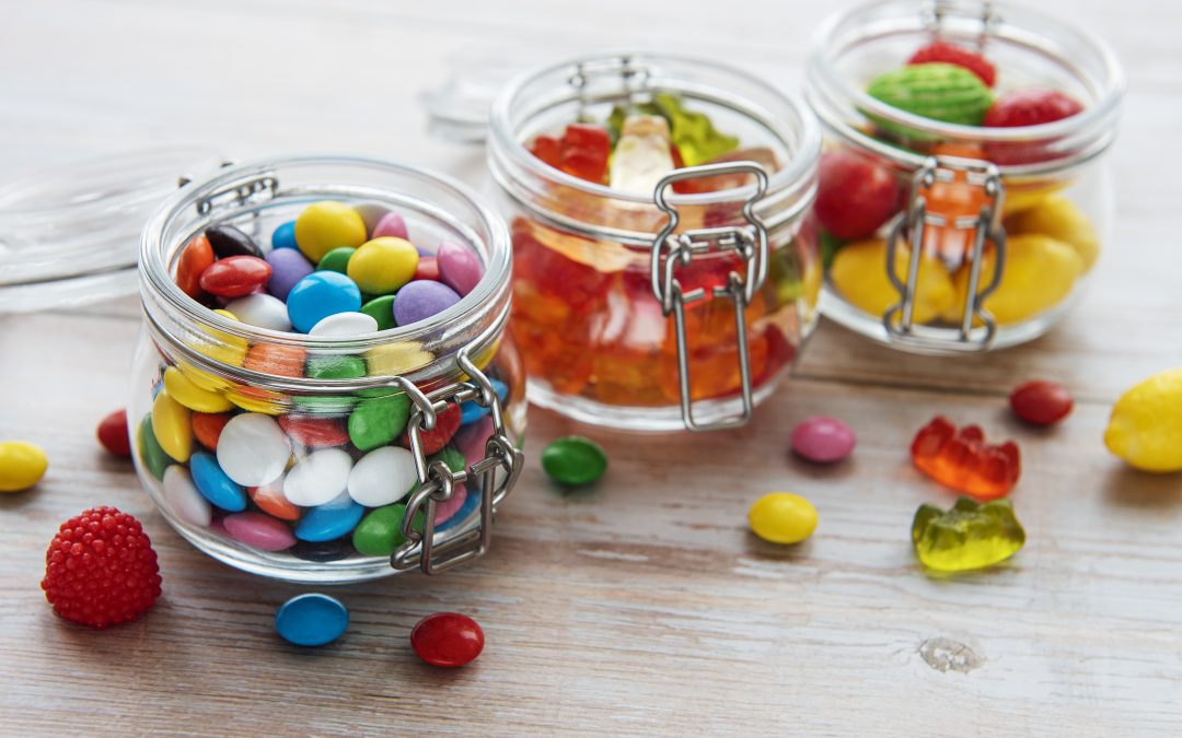
J’ai arrêté de fumer : comment gérer les envies de sucre ?
En arrêtant de fumer, il est courant d’avoir des envies de grignotage. Vos envies de sucre augmentent pour compenser le manque. Ce qui n’est pas sans conséquence pour la santé, et même pour la ligne. Il existe quelques petites astuces pour pallier ce nouveau besoin et...

Partenaires
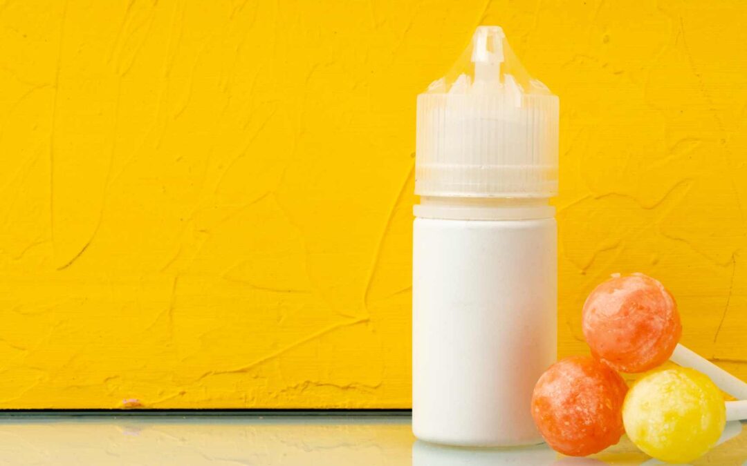
Ce grossiste CBD pourra vous fournir le E-Liquide CBD que vous recherchez ! Pour les entreprises, voici le Grossiste CBD pour les professionnels
Il est n’est pas toujours facile d’arrêter de fumer, c’est probablement même un des plus grands challenges qu’un fumeur peut rencontrer dans sa vie.
Malgré tout, j’ai réussi à vaincre la cigarette et je me suis aujourd’hui libérée d’un poids ! Cela a demandé du temps et des efforts mais le résultat en valait le coup !
C’est pour cela que j’ai décidé de créer ce blog, pour accompagner chaque fumeur dans son combat contre le tabac et pour leur partager les nouvelles passions que j’ai découvertes suite à mon arrêt de fumer !
E-cigarette
Mon avis sur les meilleurs liquides pour e-cigarette : marques et saveurs à découvrir
Avis aux amateurs de cigarettes électroniques et de nouvelles sensations gustatives ! Aujourd'hui,...

Les différents types de e-cigarettes : pod, box mod, stylo, etc.
En tant que fervents adeptes de la vape, nous sommes souvent confrontés à de nombreuses questions...
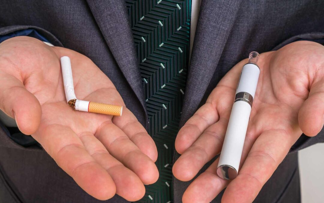
Les avantages et inconvénients de la cigarette électronique par rapport à la cigarette traditionnelle
Il est toujours difficile de parler de cigarette électronique sans évoquer la cigarette...

Les meilleures marques de e-cigarettes sur le marché : Smok, Vaporesso, Innokin, etc.
Les cigarettes électroniques sont devenues un véritable phénomène de société et une alternative...
Beauté Santé
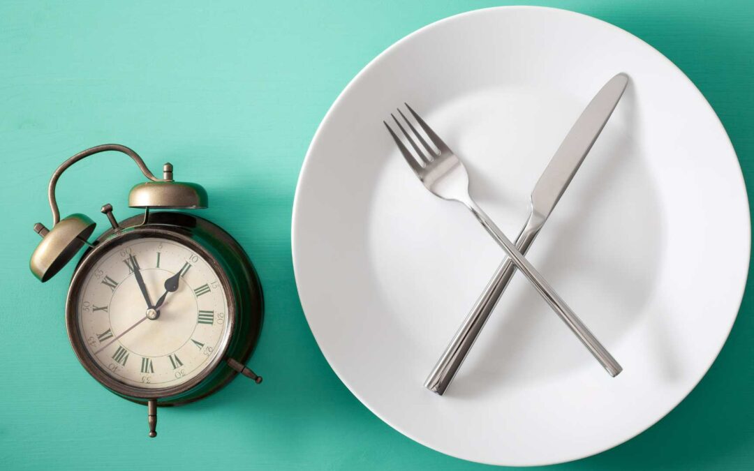
Erreurs à éviter en jeûnant : Les erreurs les plus courantes à éviter pour en tirer le maximum de bénéfices.
Le jeûne intermittent est une pratique de plus en plus populaire pour améliorer la santé, perdre...
Intégrer le jeûne intermittent : Des astuces pour l’intégrer facilement dans votre emploi du temps.
Le jeûne intermittent a gagné en popularité ces dernières années en tant que méthode efficace pour...

Jeûne et enfants : Est-il adapté pour les enfants et les jeunes ?
Le jeûne est une pratique ancestrale qui consiste à s'abstenir de manger pendant une certaine...
Jeûne et santé mentale : Comment il peut améliorer la santé mentale et la clarté mentale.
Le jeûne est une pratique ancestrale qui consiste à s'abstenir de manger pendant une période...
Bricoler

Pour marquer un nouveau départ, rien de mieux que de rénover sa maison
La décision est prise, vous arrêtez de fumer. Mais retrouver un mode de vie sain ne se fait pas en...
Eliminer les odeurs de cigarette à la maison : mon nettoyage en 4 étapes
Comme vous le savez, j’étais une grande fumeuse. Quand j’ai décidé de raccrocher, les relents des...
Astuces brico pour se débarrasser des odeurs du tabac
L’odeur laissée par une cigarette fumée peut se révéler encombrante, autant pour le fumeur que...
Food

10 recettes gourmandes aux infusions CBD
Les infusions sont prisées depuis toujours pour leurs vertus tantôt apaisantes tantôt tonifiantes....
J’ai arrêté de fumer : comment gérer les envies de sucre ?
En arrêtant de fumer, il est courant d’avoir des envies de grignotage. Vos envies de sucre...

La solution pour arrêter de fumer se trouve peut-être dans votre assiette
Ma crainte lorsque j’ai arrêté de fumer était de prendre du poids. J’utilisais souvent ma...
Sport

Comment j’ai surmonté ma peur de la vitesse en course sur circuit ?
Il est parfois difficile de comprendre l'attrait pour les sports automobiles et la vitesse, en...
Comment entretenir sa raquette de ping-pong ?
Vous êtes un passionné de ping-pong et vous souhaitez que votre raquette vous accompagne le plus...

En quoi les sports de glisse vous aideront à arrêter de fumer ?
Le sport est un allié de choix pour arrêter de fumer. Si commencer ou reprendre une activité...
Web
Ex Aequo : Tabagisme et marginalisation sociale : comment accompagner les publics les plus précaires ?
Dans un monde où les inégalités sociales et les problèmes de santé mentale sont de plus en plus...
Tabac et liberté : Tabagisme et stress, comment sortir de la dépendance ?
Le tabac est au cœur des préoccupations quotidiennes de millions de personnes à travers le monde....
Garder la pêche !
Préserver sa santé au quotidien c’est important. D’autant plus quand on a été fumeur pendant de nombreuses années. Suivez mes conseils pour garder la forme.
Trouver un équilibre parfait
Afin d’arrêter de fumer, il est primordial de trouver un équilibre optimal entre santé et mental. Certaines activités vous aideront à l’attendre. Découvrez lesquelles sur mon blog
Une bonne nutrition dans votre assiette
Quand on cherche à arrêter de fumer, il est primordial de se nourrir convenablement. Découvrez mes conseils nutritionnels